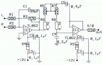
Schematic Diagram:
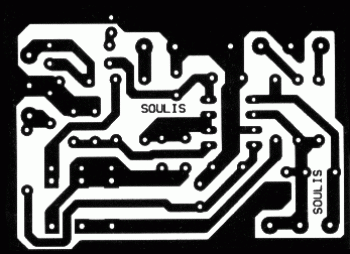
PCB Layout:
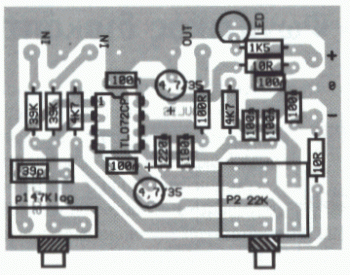
Component Placement:
Source:
http://www.high-voltage-lab.com/7/low-pass-filter-subwoofer
Visit the source page for detailed information about this low band pass circuit.
About Audio Amplifier
An audio amplifier is an electronic amplifier that amplifies low-power audio signals (signals composed primarily of frequencies between 20 - 20 000 Hz, the human range of hearing) to a level suitable for driving loudspeakers and is the final stage in a typical audio playback chain.
The preceding stages in such a chain are low power audio amplifiers which perform tasks like pre-amplification, equalization, tone control, mixing/effects, or audio sources like record players, CD players, and cassette players. Most audio amplifiers require these low-level inputs to adhere to line levels.
While the input signal to an audio amplifier may measure only a few hundred microwatts, its output may be tens, hundreds, or thousands of watts. More explanation about power audio amplifier can be found at wikipedia.org
This is a video tutorial about how to a very simple audio amplifier based on the LM386 amplifier chip. It can be built for less than $20 (or might be less than $8 in some countries) and used to amplify any low level audio signal including a guitar, bass or mp3 player.
Watch the video:


1 comment:
where is the parts list? its pretty unclear for example p2 22k what is this is it stereo pot or what?
Post a Comment